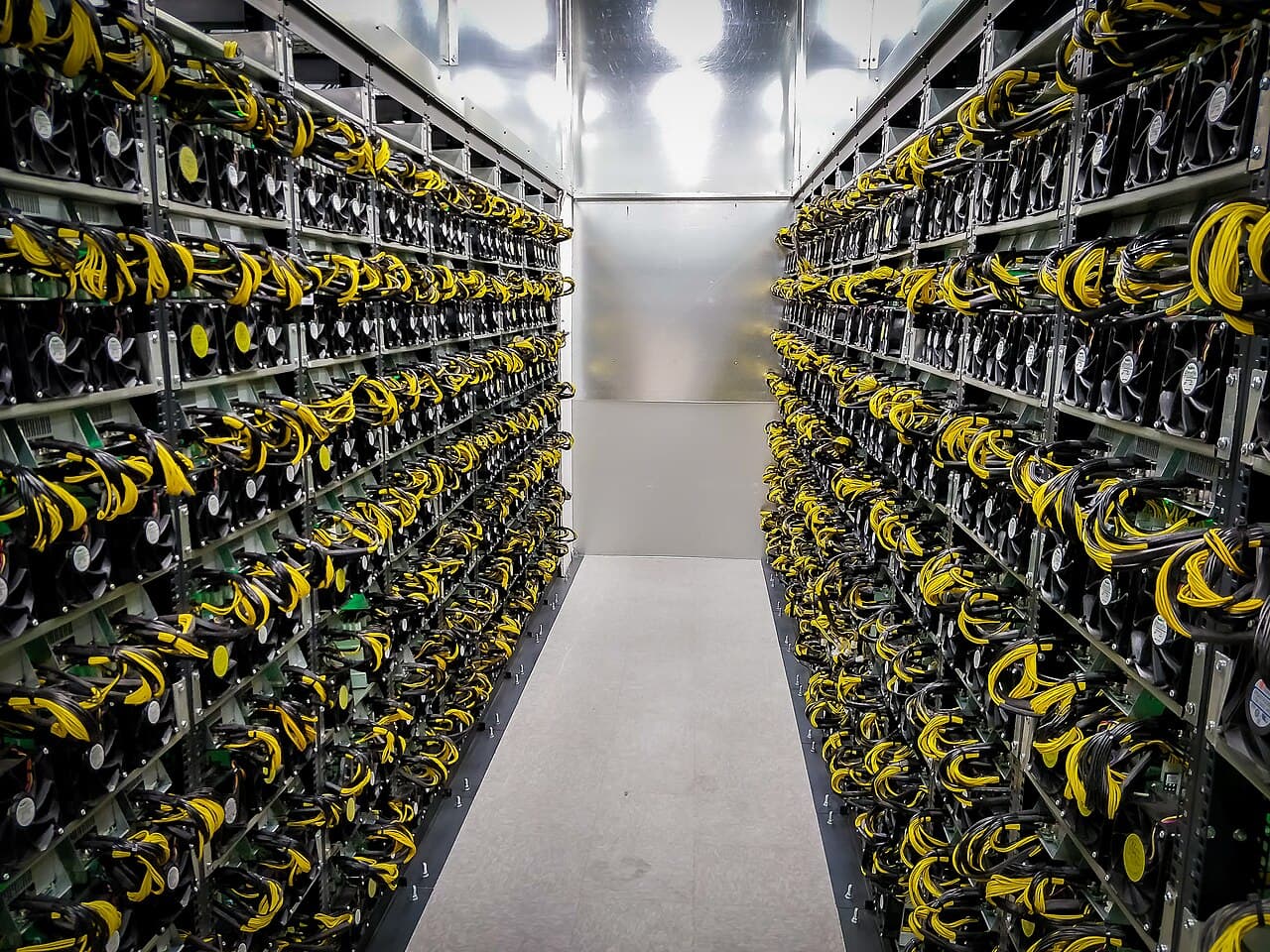
One megawatt of total site capacity runs roughly 240 to 280 air-cooled machines of about 3.5 kW each, 150 to 180 hydro machines of about 5.4 kW, or 110 to 130 machines of about 7.4 kW, depending on the overhead factor you assume (1.03 to 1.20 in the tables below). The spread comes from how much of the megawatt is consumed by cooling and electrical losses instead of miners. Dividing 1,000 kW by the nameplate wattage gives the upper limit, not the plan.
Key points
- Decide first what "1 MW" means on your site. It can be the utility supply, the transformer rating in kVA, or the miner load alone. Each gives a different count.
- Miner count = (site kW × headroom ÷ overhead factor) ÷ per-unit kW, rounded down.
- Hashrate per megawatt depends on efficiency (J/TH) and overhead, not on how large each machine is.
- Size for the manufacturer's upper power tolerance and your hottest operating condition, not the typical figure on the listing.
- Containers are limited by both slot count and electrical rating. Check both.
What 1 MW actually refers to
Three different quantities get called "1 MW".
| Meaning | What it is | Consequence |
|---|---|---|
| Total site load | Everything behind the meter, miners plus cooling, losses and auxiliaries | Miners get less than 1,000 kW |
| IT load | Power drawn by the miners only | Site must be supplied with more than 1,000 kW |
| Transformer rating | Apparent power in kVA or MVA | Real power is lower, kW = kVA × power factor |
IT load is a data-centre term for the power consumed by the computing equipment itself. Here it means the sum of the miners' wall power.
This guide treats 1 MW as total site load of 1,000 kW, because that is what a power contract or a utility connection normally limits. If your 1 MW is a miner-only figure, skip the overhead step and size the supply upward instead.
Overhead factor
Power usage effectiveness (PUE) is total site power divided by IT power. A factor of 1.10 means that for every 1.00 kW delivered to miners, the site draws 1.10 kW.
IT load = total site load ÷ overhead factor
Be careful with the phrase "10% overhead". It can mean 10% of the miner load (factor 1.10, IT load 909.1 kW) or 10% of the total (IT load 900.0 kW). This guide uses the PUE definition throughout.
What sits inside the overhead depends on the cooling method:
| Cooling method | Main overhead loads |
|---|---|
| Air | Intake and exhaust fans beyond the miners' own fans, evaporative pads or pumps where used, transformer and cable losses, network, lighting |
| Hydro | Circulation pumps, dry cooler or cooling tower fans, transformer and cable losses, controls |
| Immersion | Fluid pumps, secondary loop pumps, dry cooler fans, transformer and cable losses, controls |
Mining sites generally avoid mechanical refrigeration, so their overhead factors sit well below those of conventional data centres. The exact figure for your design is not something to copy from an article. Build it from the cooling supplier's rated fan and pump power, the transformer loss figure on its datasheet, and your climate, then measure it once the site runs. The factors in the tables below are assumptions for you to replace.
The formula
Units = floor( (site kW × headroom ÷ overhead factor) ÷ per-unit kW )
- Site kW is real power. If you only have kVA, multiply by the power factor. A 1,000 kVA transformer at an illustrative power factor of 0.95 supplies 950 kW. Take the real power factor from the miner power supply datasheet.
- Headroom is the fraction of capacity you allow yourself to use continuously, a number between 0 and 1 that you and your electrical engineer set. The tables below use 1.00 so the effect of overhead is visible on its own.
- Per-unit kW is wall power per machine, including the manufacturer's tolerance.
- floor means round down. A fraction of a miner does not run.
Worked table for 1,000 kW total
The three machines are illustrative, not specific models:
- Unit A, air-cooled, 3.5 kW and 200 TH/s, which is 3,500 ÷ 200 = 17.5 J/TH
- Unit B, hydro, 5.4 kW and 360 TH/s, which is 5,400 ÷ 360 = 15.0 J/TH
- Unit C, hydro, 7.4 kW and 500 TH/s, which is 7,400 ÷ 500 = 14.8 J/TH
| Overhead factor | IT load (kW) | Overhead (kW) | Unit A count | Unit B count | Unit C count |
|---|---|---|---|---|---|
| 1.00 (miners only) | 1,000.0 | 0.0 | 285 | 185 | 135 |
| 1.03 | 970.9 | 29.1 | 277 | 179 | 131 |
| 1.05 | 952.4 | 47.6 | 272 | 176 | 128 |
| 1.10 | 909.1 | 90.9 | 259 | 168 | 122 |
| 1.15 | 869.6 | 130.4 | 248 | 161 | 117 |
| 1.20 | 833.3 | 166.7 | 238 | 154 | 112 |
Check one cell yourself. At a factor of 1.10, IT load is 1,000 ÷ 1.10 = 909.1 kW. For Unit B, 909.1 ÷ 5.4 = 168.4, so 168 machines, which draw 168 × 5.4 = 907.2 kW.
Moving from 1.05 to 1.15 costs 24 machines of Unit A (272 down to 248). Overhead is worth designing carefully.
Resulting hashrate
Hashrate = units × TH/s per unit. 1 PH/s = 1,000 TH/s.
| Overhead factor | Unit A (PH/s) | Unit B (PH/s) | Unit C (PH/s) |
|---|---|---|---|
| 1.00 (miners only) | 57.00 | 66.60 | 67.50 |
| 1.03 | 55.40 | 64.44 | 65.50 |
| 1.05 | 54.40 | 63.36 | 64.00 |
| 1.10 | 51.80 | 60.48 | 61.00 |
| 1.15 | 49.60 | 57.96 | 58.50 |
| 1.20 | 47.60 | 55.44 | 56.00 |
There is a shortcut that skips the unit count:
TH/s per MW of total load ≈ 1,000,000 ÷ (J/TH × overhead factor)
For Unit A at 1.10 that is 1,000,000 ÷ (17.5 × 1.10) = 51,948 TH/s, or 51.9 PH/s. The table shows 51.80 PH/s because whole machines leave 2.6 kW unused.
The shortcut makes the important point. Unit C draws more than twice the power of Unit A, yet a megawatt of Unit C produces only about 18% more hashrate (61.00 against 51.80 PH/s), and that gain comes entirely from its lower J/TH. On a power-limited site, efficiency sets your hashrate. Put current network values into the calculator to see what a given hashrate earns. This guide makes no revenue estimate.
Tolerance and temperature
Listed power is a typical value under stated conditions. Bitmain's published specification for the Antminer S21, for example, gives 3,500 W at 25°C inlet air with a power tolerance of ±5%. At the upper tolerance that is 3,500 × 1.05 = 3,675 W.
Redo Unit A at 3.675 kW and a factor of 1.10. 909.1 ÷ 3.675 = 247.4, so 247 machines instead of 259. Planning on the typical figure and then discovering the upper tolerance in summer is how a site ends up tripping its main breaker or curtailing machines.
Two further effects push the same way. Fans, pumps and dry coolers work hardest on the hottest days, so the overhead factor is highest when the supply is most stressed. Firmware power modes can also raise per-unit draw above the listed figure.
Headroom is a design decision
Running a supply at 100% of its rating continuously leaves nothing for tolerance, voltage variation or measurement error. Under North American practice (NEC), continuous loads are commonly limited to 80% of a breaker's rating, which governs how many machines each branch circuit and PDU can carry. Other regions follow their own codes. Whether a similar margin applies to your transformer and main switchgear depends on the equipment ratings and the utility agreement.
Circuit, breaker and transformer sizing must be done by a qualified electrician or electrical engineer to local code. Use the formula above to scope a project, not to size conductors or protection.
How many containers
Containers = ceil( units ÷ slots per container ), rounding up.
Slot count comes from the container supplier and depends on the miner model. The slot counts below are assumptions to show the method, not the capacity of any real product. Counts use the 1.10 row, which gives 259, 168 and 122 units.
| Assumed slots per container | Unit A (259) | Unit B (168) | Unit C (122) |
|---|---|---|---|
| 100 | 3 | 2 | 2 |
| 150 | 2 | 2 | 1 |
| 200 | 2 | 1 | 1 |
| 300 | 1 | 1 | 1 |
Then check the electrical rating. A container with 200 slots filled with Unit C would draw 200 × 7.4 = 1,480 kW, more than the whole site. The lower of the slot limit and the power limit applies, and a partly filled container still carries its full pump and fan overhead. See the ASIC mining container guide for what else to specify.
Common errors
- Dividing 1,000 kW by nameplate watts and ordering that many machines.
- Treating a 1,000 kVA transformer as 1,000 kW.
- Using an overhead figure quoted for a different climate or cooling method.
- Ignoring the manufacturer's power tolerance.
- Counting slots without checking the container or PDU power rating.
- Forgetting that the meter may sit on the high-voltage side, which puts transformer losses on your bill and inside your contracted capacity.